Solution


Escalator Load Capacity

Escalator manufacturers must ensure individual steps can withstand repeated passenger loading and demanding operating conditions without excessive deflection, structural damage, or premature fatigue. Testing requires precise force measurement to evaluate step load capacity, structural integrity, and long-term durability under both static and repeated loading conditions.

Summary

  • Customer Need / Challenge

    Escalator manufacturers must ensure individual steps can withstand repeated passenger loading and demanding operating conditions without excessive deflection, structural damage, or premature fatigue. Testing requires precise force measurement to evaluate step load capacity, structural integrity, and long-term durability under both static and repeated loading conditions.

  • Interface Solution

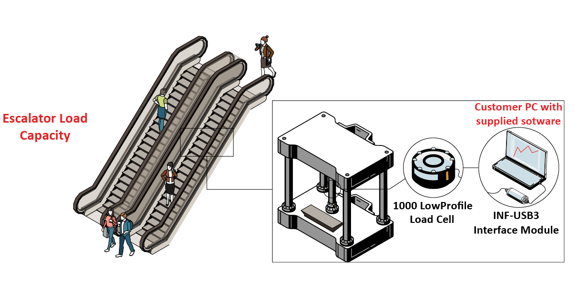
    Interface’s 1000 Fatigue-Rated Universal LowProfile Load Cell measures applied compression forces during static and cyclic escalator step testing. The force results captured is sent to the INF-USB3 Universal Serial Bus Single Channel PC Interface Module, where results can be graphed and logged on the customer’s PC with provided software.

  • Results

    Accurate force measurement enables engineers to evaluate escalator step strength, monitor fatigue performance, and identify potential structural weaknesses. Interface’s precision load cells and data acquisition solutions support repeatable testing, helping manufacturers validate designs, improve product reliability, and ensure escalator steps meet applicable load and durability requirements.

Materials


  • 1000 High Capacity Fatigue-Rated LowProfile™ Load Cell
  • INF-USB3 Universal Serial Bus Single Channel PC Interface Module with included INF-USB3 software
  • Customer’s PC or Laptop

How it Works


  1. An individual escalator step is secured within a test fixture. A hydraulic actuator applies a predetermined downward force to the step through a loading plate.
  2. Interface’s 1000 High Capacity Fatigue-Rated LowProfile™ Load Cell is installed in the press forming machine, within the punch plate.
  3. The actuator repeatedly applies and releases force to simulate long-term passenger loading.
  4. Force results are captured by the 1000, and sent to the INF-USB3 Universal Serial Bus Single Channel PC Interface Module, where results can be graphed and logged on the customer’s PC with provided software.

Download PDF